This blog documents the restoration, and conversion, of a 1965 Humber (Singer) Vogue to a fully electric vehicle. The Vogue will be powered by an 11kW(modified), 3 phase industrial AC motor, controlled by an industry standard Variable Speed Drive (VSD) or Inverter. To be able to produce the 400 volts phase to phase the VSD will need about 600 VDC of batteries. A big thanks to the contributors on the AEVA forum: http://forums.aeva.asn.au/forums/

Monday, November 29, 2010

Helping Someone Move - Charger progress

I have not had much time for the car this past week but I have been planning wiring layouts etc.
This is a 2D of the final engine bay layout. The controller has moved to the left side of the car in order to better balance left to right weight. Note the new addition (with relative position) of a 12V sealed AGM battery that will kick start the whole shebang.

I spent the weekend sealing my sister-in-law's new garage and moving delicate stuff in cars as she is moving to a new dwelling. I did manage to steal an hour or so to slightly progress with wiring the chargers. I didn't take any photos but here is the Sketchup.
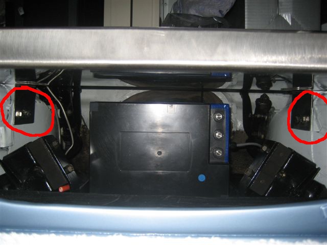
I used the spare "slot" in the second front charger tower for the terminal box that will provide power to the chargers. They are not all wired in parallel but more about that another post. The 'P' clamp is to secure the 4 charger power cables that will come in the side of the box.
Note the "Cutout for gland". It's all getting a bit tight.

Thursday, November 18, 2010

Charger 'towers' finished

I mounted the last of the seven front battery pack chargers in their brackets last night. The top slot on one of the 'towers' will be empty. I might cut it down, fill it with something cosmetic - or leave it. I will drill the holes in the bottom lips when I see exactly where they mount on the controller tray. I might have to avoid something.

I took my cordless drill battery and charger to work yesterday so I could charge it for the recommended 4-5 hours as I'm using it a lot. Also, I was trying to prevent myself from overcharging it as I have sometimes done by leaving it on all night (heaven knows why I'm building a battery powered car). You guessed it - I left it at work on charge all night - oh well. I didn't like using the power drill with cord - no speed control amongst other things.

Wednesday, November 17, 2010

How fast will it go?

The next question I get asked a lot is how fast will it go.
With my 3.89:1 differential, 185/65R13 tyres (that's tires to you USA guys) the motor will be doing about 4339 RPM at 120km/h. The motor is rated at 1465 RPM at 75% load and 50Hz. Since the controller will go up to 150Hz at it's most efficient switching rate (gets a bit complex here because it can actually go higher), then it follows that the motor can do 4395 RPM.
So it can go about 125 km/h.

How fast can it accelerate.
Another complex question. The peak power of the motor (around 70kW) is higher than the peak power my 45kW (peak) controller can deliver so initially the car will be controller limited. I have the parts to re-work my "other" controller to about 80kW so pretty much as soon as the car is safely debugged I will change over to the upgraded controller. They are physically identical - mounting, connections, everything.
The first graph is as it will go on the road, the second is with the upgraded controller.
To give these some perspective, the original Vogue did 0-100km/h in 17, 21 or 25 seconds - depending on where you get your information.


Thanks to "woody" from the AEVA forums for the extremely complex spreadsheet that takes everything - batteries, motor, controller, car Cd, weight, rolling resistance etc. - into consideration. Predictions from this spreadsheet have been verified on a real EV.

Tuesday, November 16, 2010

Range - or How far can you go on a charge?

I get asked a lot about the range of the car.
The calculations show the EVogue's projected range to be as shown in this graph.

A glossy brochure would advertise it as "Up to 160Km range". You can see that you would have to be driving at 20Km/h to get that far!
It turns out that the faster you go, the less far you can go. It has a lot to do with how "slippery" the car is when travelling through the air. The Vogue has no published figure for Cd (Coefficient of Drag) so it is yet to be determined (I have guessed at Cd = 0.45 and frontal area = 2m square).

These projections are based on flat and level driving with no start/stop and no hills so the real-world figures will be less. I'm estimating by about 15% but it will be very interesting to find out for sure. The hills don't matter too much as the motor will act as a generator (regenerative braking) when going down hills and even when stopping. In that way I get a large portion of the energy expended going up hills and accelerating, back again.

Sunday, November 14, 2010

Battery Tray Bottom and Controller Tray Mounting

I cut the slots in the 3mm Aluminium tray and siliconed it in. I used two of the packs to hold it down. These 3 packs will have either Gaffer tape or metal tape (middle one) sealing them from road grime. I have taped over the screw holes as well. The reason I can't use gaffer tape on all 3 is that the middle pack barely fits between the engine mounting plates - gaffer tape would peel off as I slid the pack into position.

I took the plunge and drilled the holes in the chassis rail extensions that Humber so generously put there for me. The controller tray is the stainless steel tray above the red circles.
This is a view in through the front of the car where the radiator block-out panel normally lives.

Close up. We just use a stainless steel 'L' bracket. I have yet to drill the holes in the the controller tray.

Motor Coupler

The motor coupler sits between the motor's 38mm shaft and the front drive shaft flange. It was mild steel so had to be painted. I chose red. I figure you have to crawl under the car to see it so I'd make it easy to spot.

Mounting the Chargers

The front battery pack chargers are going to be mounted as a little tower of 4 and another tower of 3.
I had some brackets bent up a few weeks ago.


I use the four case screws to hold the back of the charger in but I needed some 1mm aluminium to do the front.


Well they are re-doing the offices downstairs at work - and look what was left behind one night. I'm sure it was scrap. Anodized and all!


There were enough straight pieces to get my 14 of 50mm by 18mm front pieces.


Which become these. (Need holes drilled.)


The front of the charger is held in by these which allow me to remove the middle chargers without taking out all the ones on top. Just undo the rear 4 screws and the front 2 then slide the offending charger out. I haven't drilled the front 2 holes for this first one yet. I might use root nuts...

Rear Axle Breather Blocked

I changed both seals on the back axle of the Vogue a few years ago but I noticed when re-doing the brakes about a year ago (to get it back on the road), that they were still leaking a bit. Well on the hillman yahoo list, the subject of pressure building up in the back axle came up. It seems that after 45 years or so the rear axle breather hole is generally blocked and the slight pressure causes oil to be expelled either via the axle bearing seals or the differential pinion seal. It took some scraping and about 15 minutes to find it even though I had measurements of where to look. I had to wash the are in petrol to find it. Yep - blocked!
This is looking down on top of the axle casing. The black vertical pipe is a rear shock absorber.
Hope that fixes it...

Wednesday, November 10, 2010

Lower Battery Cradle gets a Bottom

I am unhappy with the way the 3 battery packs fit into the motor/battery mount in the front as there is no support for the middle of the battery packs and they tend to sag a tiny bit (these three mount on their sides). I have bought a piece of 3mm thick aluminium sheet 300 x 600mm. Of course, when I tore the rubber off the lower mount (where the packs sit) half the black paint came off. I have to clean off the rest of the glue and repaint it - then I'll silicon the aluminium sheet into the bottom of the tray (sparingly - just to stop it moving).

The packs sag into those big gaping holes. I thought the packs would be strong enough but they are not.


I have cut the sheet to fit and hopefully tonight I'll cut the slots for the battery hold-down straps.
A bit of paint then fit it in - maybe tomorrow.

Friday, November 5, 2010

This Weekend To-Do List

There's a bit of despondency in the EVogue household at the moment. We're all pretty busy and the headlining is weighing down on us. So this weekend I'm hoping to get the bow loops re-sewn (about 3 of them were cut back too far), and have another go at getting the headlining in. Apparently I should not have removed it before checking more carefully if the back section was going to fit down the rear pillars. When it's ready, I'll just put the rear bow in to check the pillar fit.

I'm still messing with the controller tray layout but I think I have pretty much covered all reasonable possibilities so, if no headlining progress, I can start drilling holes in the tray.

Oh, and Jeff from Precision Balancing just rang and my drive shaft is ready. No time today so I'll pick it up Monday.

Boot Lid Insulation

On the cup weekend (just gone), the Boot (Trunk to readers in the USA) lid received the same treatment as the bonnet.


A layer of battery pack foam. (The brown boxes are my chargers - a handy source of clamping weight until the glue sets.)


Then the silver roof insulation foil. I stopped halfway down the back so I could easily bolt lights, trim and number plates on.

I think I might treat the parcel shelf (behind the rear seats) the same way.

Thursday, November 4, 2010

The Bonnet Closes!

Putting the bonnet back on the car this past weekend was a big deal for me. As much as I have measured and estimated, I really didn't think that the bonnet was going to close with the controller on its mounting tray.
The curves of the Vogue bonnet made it very difficult to be sure.
Note the controller poking over the top. (No the wood isn't permanent).

View from left hand side of car near passenger door. The fuse/contactor box (clear lid) has to be elevated 40mm to clear the cable glands from the DC-DC converters. The single charger behind the controller will be a stack 4 high with another stack 3 high nearer to the fuse/contactor box. A few compromises but it'll all fit.

 Alongside...

The stuff is really in there! The controller cleared the bonnet by about 35mm at the front. I put my hand up through the grill opening to check. The controller tray is supported on the wood - now I can bolt it in.

The revised layout in Google Sketchup.

Added labels to one photo 25 Nov 2010.